
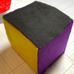
What is a ‘productivity cube’, you ask? It’s a physical device that you manually rotate to mark your changing tasks, thereby elegantly tracking your time. We built such a device for the Insum 2019 Hackathon
The concept is best understood in action:
https://www.youtube.com/embed/OtSPYfJLQBE

To be clear, this product is not new and exists in many commercials forms, for example:
Notice that these examples retail for up to $300. Keep reading to learn how you can build this time-tracking gadget for a fraction of that cost.
Productivity Cube Build Instructions
Go Shopping
You will need to select the following components ( <$50 in parts):
- Breakout Board ($10.00)
- Capacitor (cheap)
- Accelerometer ($9.95)
- 3 colored LEDS (really cheap)
- Electric Imp ($21.00)
- Breadboard ($2.92)
Note: In retrospect, we could have made this more easily and cheaply with the following combined Electric Imp and Accelerometer ($25.00)
Check your imp setup
Before doing anything else, check that the breakout board is properly configured for the power source we will be using.
In this project, we’ll use the built-in mini-USB port. Make sure that the small “jumper” is securely in place on the USB side of the three pins, as in the following photos:


The first time we built one of these ourselves (using a 9 volt battery), we had the jumper on the wrong pins when we plugged it in – and the breakout board went up in smoke! Luckily, no Imps were harmed.
Insert your imp card
Insert the Imp card into the breakout board, just as you would insert any SD card. The side with the image should face up.
Note: the card doesn’t have its own power source, so don’t expect to receive any response from the device.


Attach the breakout board to the breadboard. Here, we’ve positioned it in the top left corner of the board, to leave the most room for the other components in our circuit. The breadboard is designed so that anything placed in the same vertical column will be connected.
To begin building the circuit, add the 220 uF capacitor. The short, negative lead (also signified by the lighter stripe on the side of the capacitor) is placed in the breadboard
column associated with the GND pin on the breakout board, while the longer, positive
lead goes in the adjacent column, connecting to the VIN pin of the breakout board.
Note: You’ll have to slightly bend the longer, positive lead so that both leads will successfully make a connection to the breadboard.

Why?
The initial start-up & connection of the Imp draws more power than
normal operation, so by placing the capacitor in parallel with the power
supply, we can supplement the power supply with the charge stored in the
capacitor. You can control how frequently the device sends data. When
configured to send data at intervals of 2 minutes or greater, the device
will go into a deep sleep to conserve energy. The capacitor helps the
wake-up process go smoothly, like your morning cup of coffee.
Adding the LEDs
The LEDs are primarily for debugging purposes and you can skip this part if you don’t have LEDs on hand.
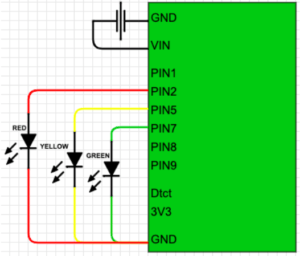
| LED | Longer lead goes in: | Shorter lead goes in: |
|---|---|---|
| Green LED | Pin7 | Ground |
| Yellow LED | Pin5 | |
| Red LED | Pin5 |
Let’s take a break from physical device configuration and prepare our database to accept and manage the productivity data we’ll be sending its way.
Configure your database
If either (1) you are a confident Oracle APEX developer or (2) you’d like to use a non-oracle database, you are welcome to skip ahead to the ‘Test your webservice’ section.
Install database objects
If you want use our database objects as a baseline, you are very welcome to install the 3 tables, 1 view, 1 package and 1 APEX application that we prepared for our hackathon:
https://github.com/hhudson/productivity_cube/tree/master/source
To install these objects, simply deploy the install.sql script into your schema.
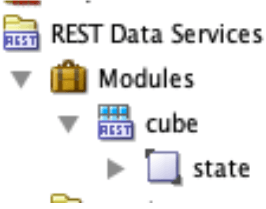
Create a REST service
I will describe how we created a RESTful service using our Oracle 18c Database. After REST-enabling our schema, we created a module ‘cube’:
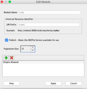
We gave our module a template we called ‘state’:
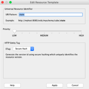
This template was then finally given a POST method to accept the Electric Imp data into our procedure:
begin
  cube_utils.change_project(p_device_id => :deviceID,
                            p_side      => :side);
end;
To review, we generated the following hierarchy of database objects:
Test your web service
You can test your web service with a curl command similar to the following (you’ll need to replace the destination URL with your own):
hayden@mac:~/$ curl -k -H "Content-Type:application/json" -X POST -d '{"deviceID":"[your device id]","side":2}' https://dev.insumlabs.com/webappsdev/hackathon2019/cube/state
(the -k is only there if you do not have a legit TLS certificate) If this curl command is successful, you should see data being inserted into your cube_time table.
Connecting Your Own Imp
Now that we have a RESTful service configured, let’s create an account at https://electricimp.com/ and download the Electric Imp app to your smartphone (the app makes connecting your imp much easier).
Information on connecting your device to a WiFi network can be found here. In our experience, it is not unusual for the process to require multiple attempts – don’t give up, we have configured hundreds of Imps, and you can too! It may help to be in a darker environment and to initiate the process as soon after the device receives power as possible. Note: The Electric Imp will not work with a 5GHz wifi network.
Pro-tip : Use the electric imp app on your phone
Once you’ve successfully, you will get the following success notification:

After connecting the Imp to the network, it can be programmed via the Imp Cloud IDE. After logging in with the account you previously created and used to Blink Up the Imp, click Create New Model (upper left corner).
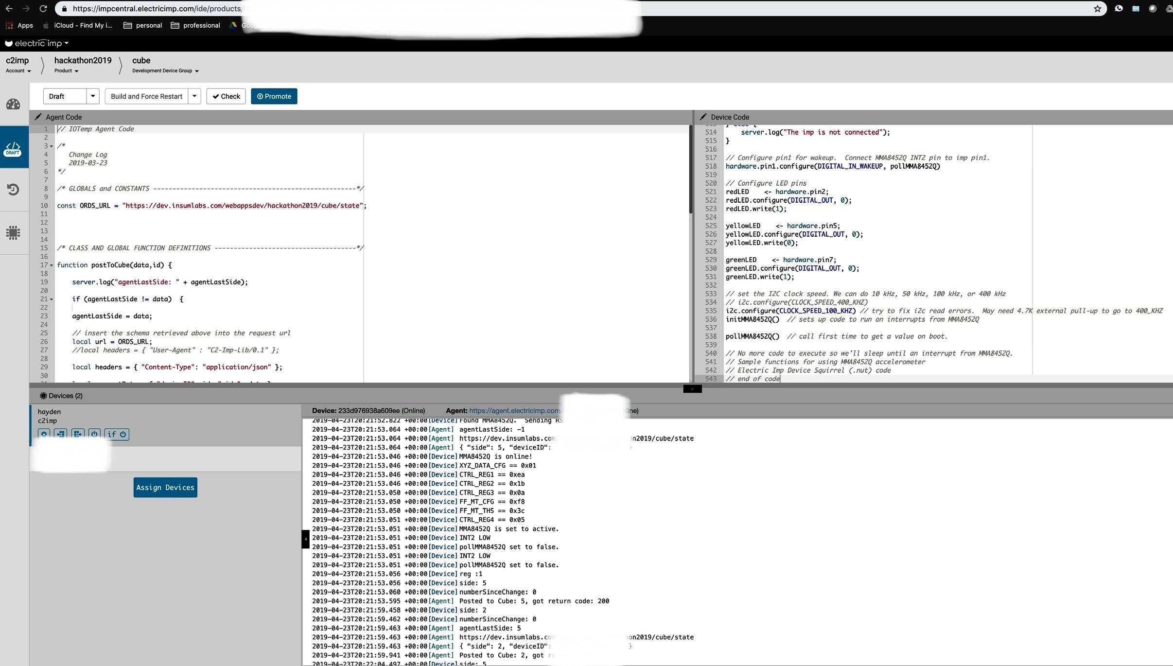
Agent code
Note: You will need to supply your own value for the ‘ORDS_URL’ to match the RESTful service you created above.
// IOTemp Agent Code

        /*
           Change Log
           2019-03-23
        */

        /* GLOBALS and CONSTANTS -----------------------------------------------------*/

        const ORDS_URL = "https://dev.insumlabs.com/webappsdev/hackathon2019/cube/state";


        /* CLASS AND GLOBAL FUNCTION DEFINITIONS -------------------------------------*/

        function postToCube(data,id) {

            server.log("agentLastSide: " + agentLastSide);

            if (agentLastSide != data)  {


            // insert the schema retrieved above into the request url
            local url = ORDS_URL;
            //local headers = { "User-Agent" : "C2-Imp-Lib/0.1" };

            local headers = { "Content-Type": "application/json" };

            local requestData = { "deviceID": id, "side": data };
            local body = http.jsonencode(requestData);

            server.log(url);
            server.log(body);

            local response = http.post(url, headers, body).sendsync();

            if(response.statuscode != 201 && response.statuscode != 200) {
                server.log("error with http request, status: " + response.statuscode);
                server.log("error with http request: " + response.body);

                server.log("retrying... ");
                local response = http.post(url, headers, body).sendsync();
                server.log("retry Posted to Cube: "+data+", got return code: "+response.statuscode) ;

                return null;
            }

            agentLastSide = data;

            //local JSONdata = http.jsondecode(response.body);

            server.log("Posted to Cube: "+data+", got return code: "+response.statuscode) ;
            } else {
            server.log("agentLastSide matches data: " + data);
            }
        }


        /* REGISTER DEVICE CALLBACKS  ------------------------------------------------*/

        device.on("data", function(datapoint) {
            postToCube(datapoint.side, datapoint.id);
        });

        /* REGISTER HTTP HANDLER -----------------------------------------------------*/

        // This agent does not need an HTTP handler

        /* RUNTIME BEGINS HERE -------------------------------------------------------*/

        server.log("Cube Agent Running");

        // Register onconnnect and ondisconnect callbacks
        device.onconnect(function() {
            server.log("Device connected to agent");
        });

        device.ondisconnect(function() {
            server.log("Device disconnected from agent");
        });


        //
        agentLastSide <- -1;

        server.log("agentLastSide on start: " + agentLastSide);
Device code
// Sample code using MMA8452Q accelerometer // Electric Imp Device Squirrel code // License: // This code is provided under the Creative Commons Attribution-ShareAlike 3.0 License // http://creativecommons.org/licenses/by-sa/3.0/us/legalcode // If you find bugs report to duppypro on github or @duppy #MMA8452Q on twitter // If you find this useful, send a good word to @duppy #MMA8452Q // Thanks to @jayrz for finding the first bug. ///////////////////////////////////////////////// // global constants and variables const versionString = "MMA8452Q Sample v00.01.2013-10-29a" ID <- hardware.getdeviceid(); //const accelChangeThresh = 500 // change in accel per sample to count as movement. Units of milliGs pollMMA8452QBusy <- false // guard against interrupt handler collisions FIXME: Is this necessary? Debugging why I get no EA_BIT set error sometimes //pollMMA8452QBusy <- true // hhh guard against interrupt handler collisions FIXME: Is this necessary? Debugging why I get no EA_BIT set error sometimes /////////////////////////////////////////////// // constants for MMA8452Q i2c registers // the slave address for this device is set in hardware. Creating a variable to save it here is helpful. // The SparkFun breakout board defaults to 0x1D, set to 0x1C if SA0 jumper on the bottom of the board is set const MMA8452Q_ADDR = 0x1D // A '<< 1' is needed. I add the '<< 1' in the helper functions. //const MM8452Q_ADDR = 0x1C // Use this address if SA0 jumper is set. const STATUS = 0x00 const ZYXOW_BIT = 0x7 // name_BIT == BIT position of name const ZYXDR_BIT = 0x3 const OUT_X_MSB = 0x01 const SYSMOD = 0x0B const SYSMOD_STANDBY = 0x00 const SYSMOD_WAKE = 0x01 const SYSMOD_SLEEP = 0x02 const INT_SOURCE = 0x0C const SRC_ASLP_BIT = 0x7 const SRC_FF_MT_BIT = 0x2 const SRC_DRDY_BIT = 0x0 const WHO_AM_I = 0x0D const I_AM_MMA8452Q = 0x2A // read addr WHO_AM_I, expect I_AM_MMA8452Q const XYZ_DATA_CFG = 0x0E const FS_2G = 0x00 const FS_4G = 0x01 const FS_8G = 0x02 const HPF_OUT_BIT = 0x5 const HP_FILTER_CUTOFF = 0x0F const FF_MT_CFG = 0x15 const ELE_BIT = 0x7 const OAE_BIT = 0x6 const XYZEFE_BIT = 0x3 // numBits == 3 (one each for XYZ) const XYZEFE_ALL = 0x07 // enable all 3 bits const FF_MT_SRC = 0x16 const EA_BIT = 0x7 const FF_MT_THS = 0x17 const DBCNTM_BIT = 0x7 const THS_BIT = 0x0 // numBits == 7 const FF_MT_COUNT = 0x18 const ASLP_COUNT = 0x29 const CTRL_REG1 = 0x2A const ASLP_RATE_BIT = 0x6 // numBits == 2 const ASLP_RATE_12p5HZ = 0x1 const ASLP_RATE_1p56HZ = 0x3 const DR_BIT = 0x3 // numBits == 3 const DR_12p5HZ = 0x5 const DR_1p56HZ = 0x7 const LNOISE_BIT = 0x2 const F_READ_BIT = 0x1 const ACTIVE_BIT = 0x0 const CTRL_REG2 = 0x2B const ST_BIT = 0x7 const RST_BIT = 0x6 const SMODS_BIT = 0x3 // numBits == 2 const SLPE_BIT = 0x2 const MODS_BIT = 0x0 // numBits == 2 const MODS_NORMAL = 0x00 const MODS_LOW_POWER = 0x03 const CTRL_REG3 = 0x2C const WAKE_FF_MT_BIT = 0x3 const IPOL_BIT = 0x1 const CTRL_REG4 = 0x2D const INT_EN_ASLP_BIT = 0x7 const INT_EN_LNDPRT_BIT= 0x4 const INT_EN_FF_MT_BIT = 0x2 const INT_EN_DRDY_BIT = 0x0 const CTRL_REG5 = 0x2E // helper variables for MMA8452Q. These are not const because they may have reason to change dynamically. i2cRetryPeriod <- 1.0 // seconds to wait before retrying a failed i2c operation //hhh maxG <- FS_4G // what scale to get G readings i2c <- hardware.i2c89 // now can use i2c.read() /////////////////////////////////////////////// //define functions // start with fairly generic i2c helper functions function readBitField(val, bitPosition, numBits){ // works for 8bit registers // bitPosition and numBits are not bounds checked return (val >> bitPosition) & (0x00FF >> (8 - numBits)) } function readBit(val, bitPosition) { return readBitField(val, bitPosition, 1) } function writeBitField(val, bitPosition, numBits, newVal) { // works for 8bit registers // newVal is not bounds checked //server.log("writeBitField = val: "+writeBitField+"/ bitPosition: "+bitPosition+" / numBits: "+numBits+" / newVal: "+newVal) return (val & (((0x00FF >> (8 - numBits)) << bitPosition) ^ 0x00FF)) | (newVal << bitPosition) } function writeBit(val, bitPosition, newVal) { return writeBitField(val, bitPosition, 1, newVal) } // Read a single byte from addressToRead and return it as a byte. (The '[0]' causes a byte to return) function readReg(addressToRead) { return readSequentialRegs(addressToRead, 1)[0] } // Writes a single byte (dataToWrite) into addressToWrite. Returns error code from i2c.write // Continue retry until success. Caller does not need to check error code function writeReg(addressToWrite, dataToWrite) { //server.log("writeReg = addressToWrite :"+addressToWrite+" / dataToWrite :"+dataToWrite); local err = null while (err == null) { err = i2c.write(MMA8452Q_ADDR << 1, format("%c%c", addressToWrite, dataToWrite)) // server.log(format("i2c.write addr=0x%02x data=0x%02x", addressToWrite, dataToWrite)) if (err == null) { server.error("i2c.write of value " + format("0x%02x", dataToWrite) + " to " + format("0x%02x", addressToWrite) + " failed.") imp.sleep(i2cRetryPeriod) server.error("retry i2c.write") } } return err } // Read numBytes sequentially, starting at addressToRead // Continue retry until success. Caller does not need to check error code function readSequentialRegs(addressToRead, numBytes) { local data = null while (data == null) { data = i2c.read(MMA8452Q_ADDR << 1, format("%c", addressToRead), numBytes) if (data == null) { server.error("i2c.read from " + format("0x%02x", addressToRead) + " of " + numBytes + " byte" + ((numBytes > 1) ? "s" : "") + " failed.") imp.sleep(i2cRetryPeriod) server.error("retry i2c.read") } } return data } // now functions unique to MMA8452Q function readAccelData() { //server.log("readAccelData"); local rawData = null // x/y/z accel register data stored here, 3 bytes local axisVal = null local accelData = array(3) local side = null local i local val rawData = readSequentialRegs(OUT_X_MSB, 3) // Read the three raw data registers into data array foreach (i, val in rawData) { axisVal = math.floor(1000.0 * ((val < 128 ? val : val - 256) / ((64 >> maxG) + 0.0))) accelData[i] = axisVal // HACK: in above calc maxG just happens to be (log2(full_scale) - 1) see: const for FS_2G, FS_4G, FS_8G //convert to signed integer milliGs } return accelData } // Reset the MMA8452Q function MMA8452QReset() { local reg do { reg = readReg(WHO_AM_I) // Read WHO_AM_I register if (reg == I_AM_MMA8452Q) { server.log("Found MMA8452Q. Sending RST command...") break } else { server.error("Could not connect to MMA8452Q: WHO_AM_I reg == " + format("0x%02x", reg)) imp.sleep(i2cRetryPeriod) } } while (true) // send reset command writeReg(CTRL_REG2, writeBit(readReg(CTRL_REG2), RST_BIT, 1)) do { reg = readReg(WHO_AM_I) // Read WHO_AM_I register if (reg == I_AM_MMA8452Q) { server.log("MMA8452Q is online!") break } else { server.error("Could not connect to MMA8452Q: WHO_AM_I reg == " + format("0x%02x", reg)) imp.sleep(i2cRetryPeriod) } } while (true) } function MMA8452QSetActive(mode) { server.log("MMA8452Q is set to active.") // Sets the MMA8452Q active mode. // 0 == STANDBY for changing registers // 1 == ACTIVE for outputting data writeReg(CTRL_REG1, writeBit(readReg(CTRL_REG1), ACTIVE_BIT, mode)) } function initMMA8452Q() { // Initialize the MMA8452Q registers // See the many application notes for more info on setting all of these registers: // http://www.freescale.com/webapp/sps/site/prod_summary.jsp?code=MMA8452Q local reg MMA8452QReset() // Sometimes imp card resets and MMA8452Q keeps power // Must be in standby to change registers // in STANDBY already after RESET//MMA8452QSetActive(0) // Set up the full scale range to 2, 4, or 8g. // FIXME: assumes HPF_OUT_BIT in this same register always == 0 writeReg(XYZ_DATA_CFG, maxG) server.log(format("XYZ_DATA_CFG == 0x%02x", readReg(XYZ_DATA_CFG))) // setup CTRL_REG1 reg = readReg(CTRL_REG1) reg = writeBitField(reg, ASLP_RATE_BIT, 2, ASLP_RATE_1p56HZ) reg = writeBitField(reg, DR_BIT, 3, DR_12p5HZ) // leave LNOISE_BIT as default off to save power // Set Fast read mode to read 8bits per xyz instead of 12bits reg = writeBit(reg, F_READ_BIT, 1) // set all CTRL_REG1 bit fields in one i2c write writeReg(CTRL_REG1, reg) server.log(format("CTRL_REG1 == 0x%02x", readReg(CTRL_REG1))) // setup CTRL_REG2 reg = readReg(CTRL_REG2) // set Oversample mode in sleep reg = writeBitField(reg, SMODS_BIT, 2, MODS_LOW_POWER) // Enable Auto-SLEEP //reg = writeBit(reg, SLPE_BIT, 1) // Disable Auto-SLEEP reg = writeBit(reg, SLPE_BIT, 0) // set Oversample mode in wake reg = writeBitField(reg, MODS_BIT, 2, MODS_LOW_POWER) // set all CTRL_REG2 bit fields in one i2c write writeReg(CTRL_REG2, reg) server.log(format("CTRL_REG2 == 0x%02x", readReg(CTRL_REG2))) // setup CTRL_REG3 reg = readReg(CTRL_REG3) // allow Motion to wake from SLEEP reg = writeBit(reg, WAKE_FF_MT_BIT, 1) // change Int Polarity reg = writeBit(reg, IPOL_BIT, 1) // set all CTRL_REG3 bit fields in one i2c write writeReg(CTRL_REG3, reg) server.log(format("CTRL_REG3 == 0x%02x", readReg(CTRL_REG3))) // setup FF_MT_CFG reg = readReg(FF_MT_CFG) // enable ELE_BIT to latch FF_MT_SRC events reg = writeBit(reg, ELE_BIT, 1) // enable Motion detection (not Free Fall detection) reg = writeBit(reg, OAE_BIT, 1) // enable on all axis x, y, and z reg = writeBitField(reg, XYZEFE_BIT, 3, XYZEFE_ALL) // set all FF_MT_CFG bit fields in one i2c write writeReg(FF_MT_CFG, reg) server.log(format("FF_MT_CFG == 0x%02x", readReg(FF_MT_CFG))) // setup Motion threshold to n*0.063. (16 * 0.063 == 1G) writeReg(FF_MT_THS, 60) // FIXME: this is a shortcut and assumes DBCNTM_BIT is 0 server.log(format("FF_MT_THS == 0x%02x", readReg(FF_MT_THS))) // setup sleep counter, the time in multiples of 320ms of no activity to enter sleep mode //dont' use ASLP_COUNT for now, use change in prev AccelData reading //writeReg(ASLP_COUNT, 10) // 10 * 320ms = 3.2 seconds //Enable Sleep interrupts // writeReg(CTRL_REG4, writeBit(readReg(CTRL_REG4), INT_EN_ASLP_BIT, 1)) //Enable Motion interrupts writeReg(CTRL_REG4, writeBit(readReg(CTRL_REG4), INT_EN_FF_MT_BIT, 1)) // Enable interrupts on every new data writeReg(CTRL_REG4, writeBit(readReg(CTRL_REG4), INT_EN_DRDY_BIT, 1)) server.log(format("CTRL_REG4 == 0x%02x", readReg(CTRL_REG4))) MMA8452QSetActive(1) // Set to active to start reading } // initMMA8452Q // now application specific functions function pollMMA8452Q() { //server.log("pollMMA8452Q invoked."); local xyz local x local y local z local prevX local prevY local prevZ local xDiff local yDiff local zDiff local reg local prevPrevSide local prevSide; local side // added by anton local datapoint local numberSinceChange = 0; local changeCounter = 0; // end added by anton while (pollMMA8452QBusy) { //server.log("pollMMA8452QBusy collision") //server.log("hello") // wait herer unitl other instance of int handler is done // FIXME: I never see this error, probably not neessary, just being paranoid. } pollMMA8452QBusy = true // mark as busy if (hardware.pin1.read() == 1) { // only react to low to high edge //server.log("pin1 is 1") //FIXME: do we need to check status for data ready in all xyz?//log(format("STATUS == 0x%02x", readReg(STATUS)), 80) reg = readReg(INT_SOURCE) server.log("reg :"+reg) //while (reg != 0x00)//hhh while (1 == 1) { // server.log(format("INT_SOURCE == 0x%02x", reg)) if (readBit(reg, SRC_DRDY_BIT) == 0x1) { xyz = readAccelData() // this clears the SRC_DRDY_BIT prevSide = side //server.log("previsou side: "+ prevSide) if (xyz[0] == -1000) { side = 4 //server.log("side 4") } else if (xyz[0] > 960) { side = 3 //server.log("side 3") } else if (xyz[1] == -1000) { side = 1 //server.log("side 5") } else if (xyz[1] > 960) { side = 2 //server.log("side 2") } else if (xyz[2] == -1000) { side = 5 //server.log("side 1") } else if (xyz[2] > 960) { side = 6 //server.log("side 6") } numberSinceChange = numberSinceChange + 1; if (numberSinceChange == 50) { // send every 100 checks even if it has not changed datapoint = { "id" : ID, "side" : side } agent.send("data",datapoint); changeCounter = changeCounter +1; server.log("changeCounter: " + (changeCounter * 50) ); numberSinceChange = 0; } if (side != prevSide) { numberSinceChange = 0; changeCounter = 0; server.log("side: "+ side) server.log("numberSinceChange: " + numberSinceChange); yellowLED.write(1); datapoint = { "id" : ID, "side" : side } agent.send("data",datapoint); } // do something with xyz data here } if (readBit(reg, SRC_FF_MT_BIT) == 0x1) { server.log("Interrupt SRC_FF_MT_BIT") reg = readReg(FF_MT_SRC) // this clears SRC_FF_MT_BIT imp.setpowersave(false) // go to low latency mode because we detected motion } if (readBit(reg, SRC_ASLP_BIT) == 0x1) { reg = readReg(SYSMOD) // this clears SRC_ASLP_BIT // server.log(format("Entering SYSMOD 0x%02x", reg)) } reg = readReg(INT_SOURCE) imp.sleep(0.25); yellowLED.write(0); } // while (reg != 0x00) } else { server.log("INT2 LOW") } pollMMA8452QBusy = false; // clear so other inst of int handler can run server.log("pollMMA8452Q set to false."); //greenLED.write(0); //local timer = imp.wakeup(0.5, pollMMA8452Q(side)); // anton let it sleep a little } // pollMMA8452Q function disconnectHandler(reason) { if (reason != SERVER_CONNECTED) { // Server is not connected, so switch on the 'disconnected' LED... redLED.write(0); server.log("disconnect_reason: " + reason); // ... and attempt to reconnect // Note that we pass in the same callback we use // for unexpected disconnections server.connect(disconnectHandler, 5); server.log("disconnect_reason repeat: " + reason); // Set the state flag so that other parts of the // application know that the device is offline disconnectedFlag = true; } else { // Server is connected, so turn the 'disconnected' LED off // and update the state flag redLED.write(1); disconnectedFlag = false; } } //////////////////////////////////////////////////////// // first code starts here //imp.setpowersave(true) // start in low power mode. imp.setpowersave(false) // start in low power mode. hhh doesn't seem to do anything // Optimized for case where wakeup was caused by periodic timer, not user activity // Register with the server //imp.configure("MMA8452Q 1D6", [], []) // One 6-sided Die // no in and out []s anymore, using Agent messages // Send status to know we are alive //server.log("BOOTING " + versionString + " " + hardware.getimpid() + "/" + imp.getmacaddress()) server.log("BOOTING " + versionString + " " + hardware.getdeviceid() + "/" + imp.net.info()) server.log("imp software version : " + imp.getsoftwareversion()) // BUGBUG: below needed until newer firmware!? See http://forums.electricimp.com/discussion/comment/4875#Comment_2714 // imp.enableblinkup(true) // added by Anton //server.setsendtimeoutpolicy(RETURN_ON_ERROR, WAIT_TIL_SENT, 30); server.onunexpecteddisconnect(disconnectHandler); local netData = imp.net.info(); if ("active" in netData) { local type = netData.interface[netData.active].type; // We have an active network connection - what type is it? if (type == "cell") { // The imp is on a cellular connection local imei = netData.interface[netData.active].imei; server.log("The imp has IMEI " + imei + " and is connected via cellular"); } else { // The imp is connected by WiFi or Ethernet local ip = netData.ipv4.address; local theSSID = netData.interface[netData.active].ssid; server.log("The imp has IP address " + ip + " and is connected via " + type); server.log("The imp has SSID " + theSSID); } if (netData.interface.len() > 1) { // The imp has more than one possible network interface // so note the second (disconnected) one local altType = netData.active == 0 ? netData.interface[1].type : netData.interface[0].type; server.log("(It can also connect via " + altType + ")"); } } else { server.log("The imp is not connected"); } // Configure pin1 for wakeup. Connect MMA8452Q INT2 pin to imp pin1. hardware.pin1.configure(DIGITAL_IN_WAKEUP, pollMMA8452Q) // Configure LED pins redLED <- hardware.pin2; redLED.configure(DIGITAL_OUT, 0); redLED.write(1); yellowLED <- hardware.pin5; yellowLED.configure(DIGITAL_OUT, 0); yellowLED.write(0); greenLED <- hardware.pin7; greenLED.configure(DIGITAL_OUT, 0); greenLED.write(1); // set the I2C clock speed. We can do 10 kHz, 50 kHz, 100 kHz, or 400 kHz // i2c.configure(CLOCK_SPEED_400_KHZ) i2c.configure(CLOCK_SPEED_100_KHZ) // try to fix i2c read errors. May need 4.7K external pull-up to go to 400_KHZ initMMA8452Q() // sets up code to run on interrupts from MMA8452Q pollMMA8452Q() // call first time to get a value on boot. // No more code to execute so we'll sleep until an interrupt from MMA8452Q. // Sample functions for using MMA8452Q accelerometer // Electric Imp Device Squirrel (.nut) code // end of code
Almost there – nothing should be happening on your Imp dashboard yet, though, because we haven’t connected the accelerometer up yet.
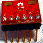
Prepare your accelerometer
If you haven’t already, you’ll need to solder headers to your Productivity Cube accelerometer, as shown in the following photo:
Connect accelerometer to Imp
You’ll need to connect your accelerometer to your electric imp on your breadboard with the following connections:
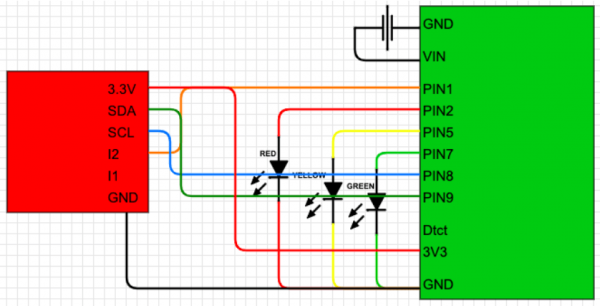
| Component | Accelerometer | Imp |
|---|---|---|
| Black jumper | Ground | Ground |
| Orange jumper | I2 | Pin1 |
| Blue jumper | SCL | Pin8 |
| Green jumper | SDA | Pin9 |
| Red jumper | 3.3V | 3V3 |
Before Powering Up Your Productivity Cube
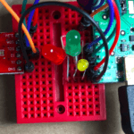
Finally, it’s time to turn on the device! Before you plug the mini-USB into the port on the breakout board, double check that the LEDs and resistors are properly connected, that the capacitor is oriented correctly, and the power-jumper is placed on the two USB pins.
Once you’ve powered up, you should start seeing activity in the Electric imp Dashboard as well as see data being passed into your cube_time table.
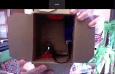
Finalize your Productivity Cube: Put your gear in a box
If you peel off the backing of the breadboard, you’ll find it will stick solidly to any surface (be careful).
We used an empty kleenex box as you saw in our video:
Productivity Cube Thanks and Acknowledgments
Thanks to Christine Nielsen for many of the photographs. Much of this blog post is a wholesale ripoff of Anton Nielsen’s earlier post
Thanks to ‘Duppy’ for this excellent git repo.
Thanks also to Sparkfun for this helpful tutorial.
